CE-DP1000V1

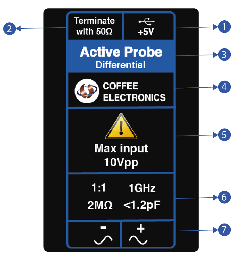
- 1.0 GHz bandwidth
- 2 MΩ input resistance
- < 1.2pF Input Capacitance
- ±2V Input Dynamic Range
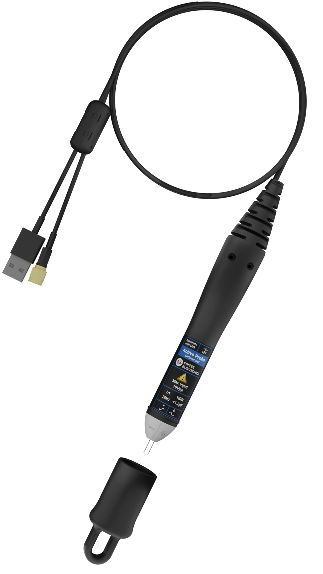
- Universal power supply using USB cable
Applications:
- Ideal for digital system design, component design / characterization, and educational research applications
- Active probe for high frequency applications
- Can be used for single-ended signal with better common mode rejection
General Information:
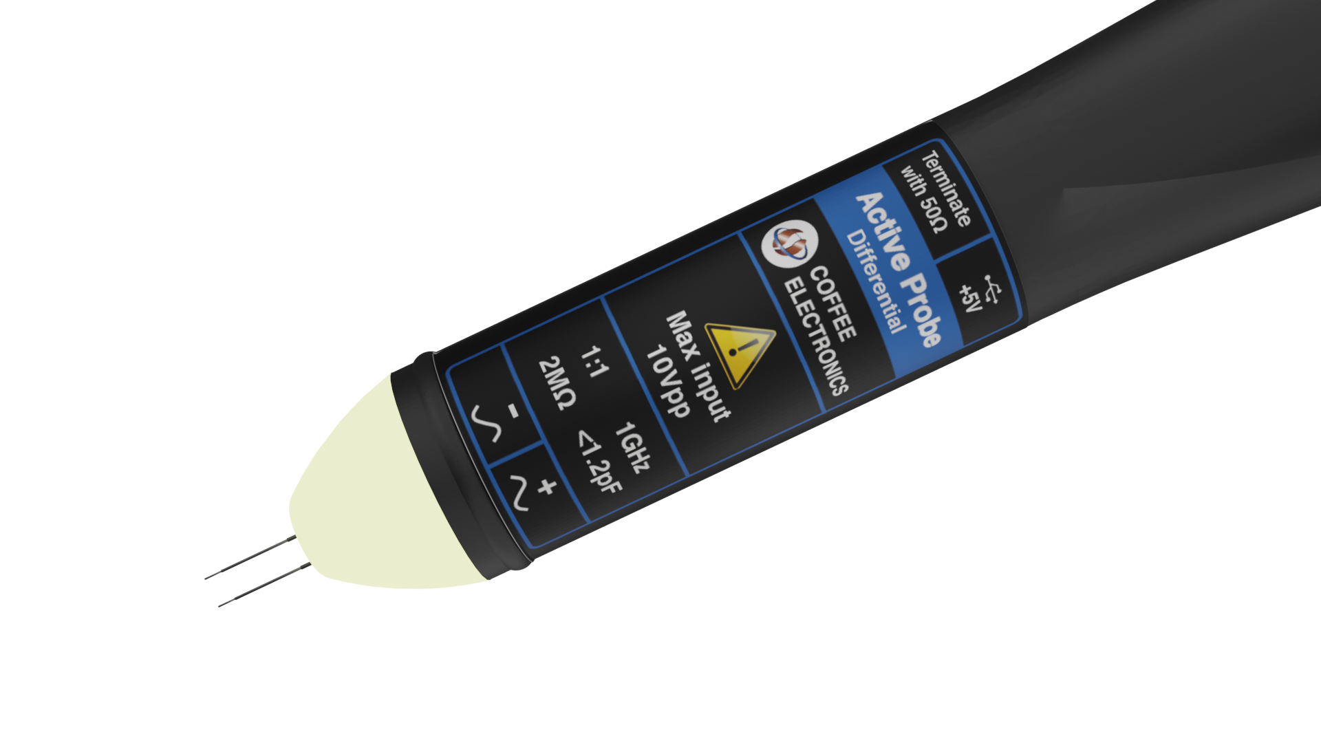
The CE-DP1000V1, with a 1.0 GHz bandwidth, is ideal for high-frequency measurements in digital design. Boasting 1:1 ±2% attenuation for accurate DC signal readings, it offers USB connectivity and an SMA connector for versatility. A smart choice for both educational and design applications, it comes with an illuminated LED and a convenient cap.
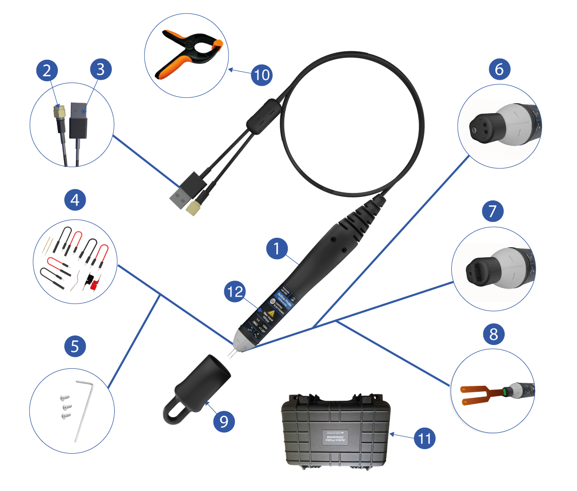
Set of CE-DP1000V1 active probe consist of:
| Image | Description | ||||||||||||||||||||||||
|---|---|---|---|---|---|---|---|---|---|---|---|---|---|---|---|---|---|---|---|---|---|---|---|---|---|
 |
|
Sticker General info
| Image | Description | ||||||||||||||
|---|---|---|---|---|---|---|---|---|---|---|---|---|---|---|---|
 |
|
Features
LED tip illumination
When the probe is powered, the tip illuminates automatically to improve visibility of the measurement point. The light is soft and localized
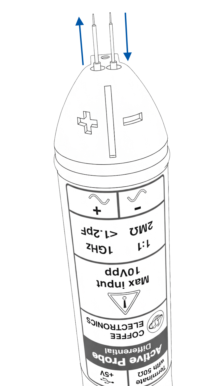
Pogo pins
The pogo pins can be gently installed or removed from the probe tip. Insert them aligned into the designated holes and avoid excessive force to prevent damage.
Modes
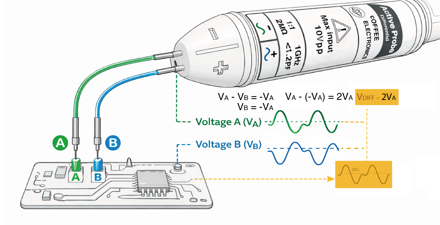
Differential
In differential mode, the probe measures the voltage between two points of the circuit (Tip A and Tip B). The displayed result corresponds to the difference between both voltages: VDIFF = VA − VB This enables accurate differential signal measurement while minimizing noise and ground-related interference.
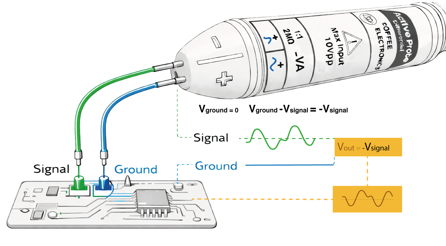
Singled Ended
Although the Active Differential Probe is configured for differential operation, it can also be used in single-ended (SE) mode when required. In this configuration, the positive tip is connected to the signal and the negative tip is connected to ground.
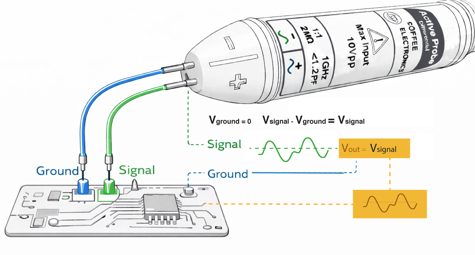
Reversing the probe connections will invert the polarity of the measured signal.